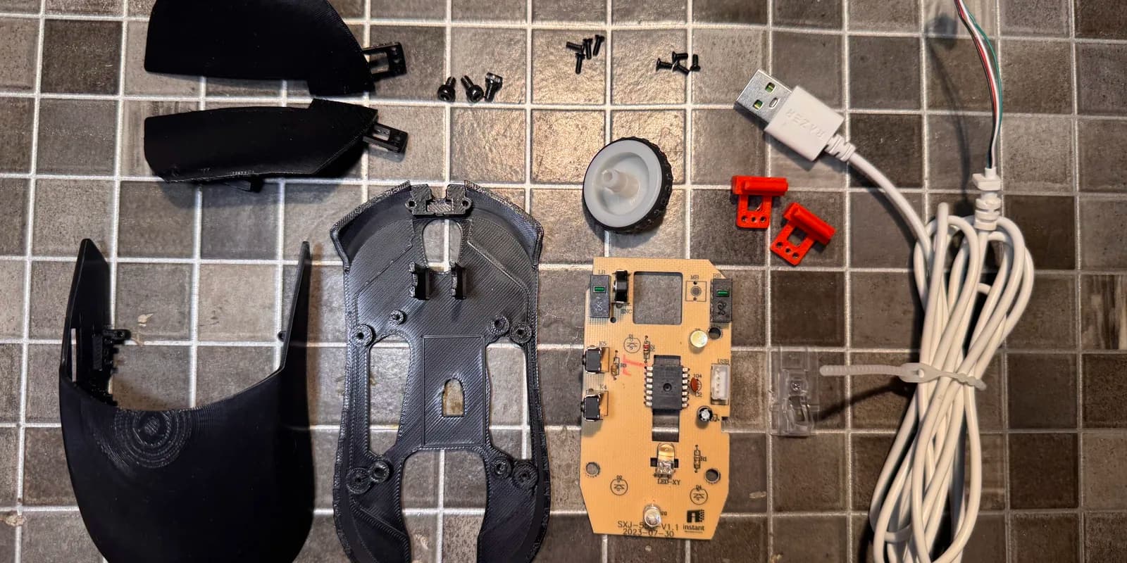
A friend tried to move the internals of his Razer DeathAdder Elite into a printed shell. The operation failed and the project died. I inherited the electronics from a second mouse in that pile — a DeathAdder Essential — and built a new body around them. It works. It is also, by any reasonable standard, a design war crime. I published it anyway, and this is the honest write-up of why.
The inheritance
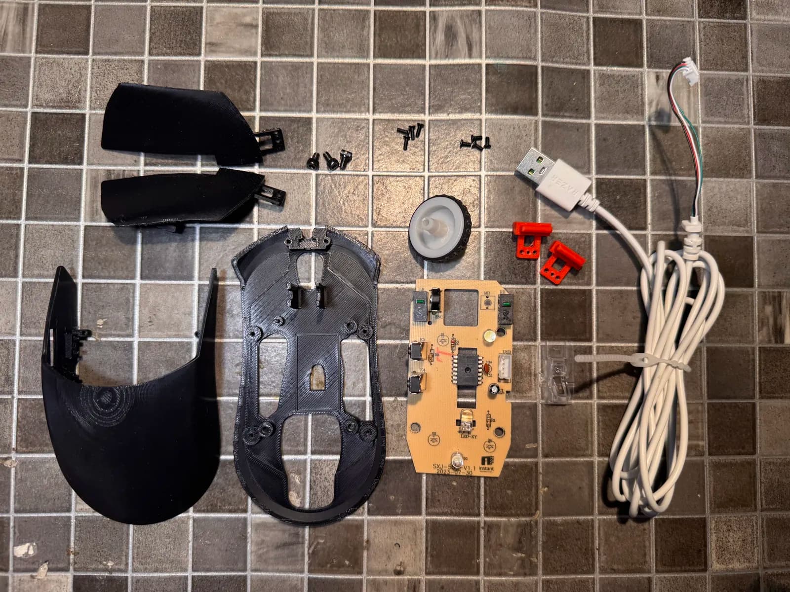
What I received was the whole nervous system of a mouse and no body: the PCB with the sensor and the switches on it, the cable, the clear plastic sensor lens, and a scroll encoder. Everything that makes a mouse a mouse, apart from the part your hand touches.
Buying a new mouse would have cost less than the filament and the screws. That was never the point. The point was that a working sensor and a working USB cable were sitting in a drawer, and the only thing between them and a usable mouse was a shape.
What a mouse shell actually has to hold
Before this I assumed a mouse shell was a plastic lid. It is not. It is a fixture that has to hold five different things in the right place relative to each other, and most of them have no tolerance to give:
- The sensor and its lens. The optical sensor reads the surface through a moulded clear lens, and the lens has to sit at the exact height and angle the original shell held it at. Get this wrong and the mouse tracks badly or not at all. This is the one part I did not dare redesign — the lens drops into a seat in the base plate and the geometry copies the donor.
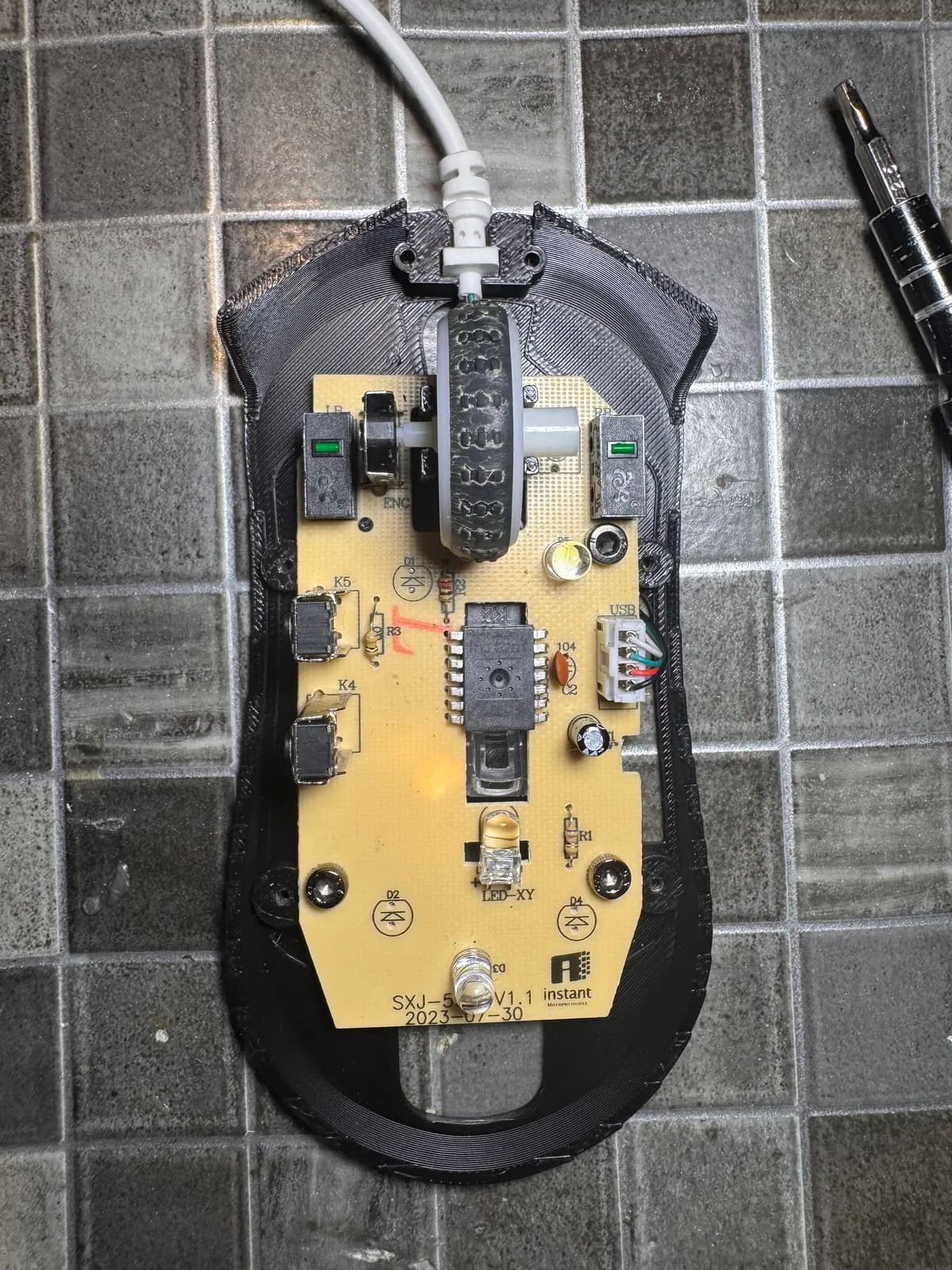
- The PCB mounting holes. Three M3 screws fix the board, and they set the position of everything else. Every other dimension in the shell is measured from these.
- The switch plungers. The main buttons do not press the switches directly. A printed lever arm, held by a screw, transfers your finger onto the switch. Its pivot, its length and how far it travels decide whether the click feels crisp or like pressing a sponge.
- The scroll encoder. The wheel has to be concentric with the encoder shaft and square to the shell opening. A degree of tilt is visible to the eye and annoying to the finger.
- The cable exit. The strain relief has to be anchored so that pulling the cable moves the mouse instead of the board.
Four of those five I got acceptably right. You can guess from the list which one I did not.
Designing it
I did not start from a blank file. The shape is a remix of EOS, a barebones mouse shell — all credit for the base geometry goes to its author. I reshaped it until the Essential internals fitted, which in practice meant pushing surfaces around in Rhino until nothing collided, then checking again. The whole thing is NURBS surfaces — no SubD anywhere — and I now think that choice cost me more than it saved.
That order of operations — fit first, worry about printing never — is exactly where the trouble started. Every decision optimised for "does the board clear this wall" and none for "can a nozzle reach this". The result prints, but only under a forest of supports.
Why the Rhino file is in the download
Parts and assembly
Four printed parts, two optional printed side buttons, eleven screws in three sizes, and the donor electronics. The part names below match the STL filenames.
| Screw | Qty | Job |
|---|---|---|
| M3x5 | 3 | Hold the PCB down to the base plate |
| M2x4 | 4 | Hold the spring plastics that press the buttons |
| M2x8 | 4 | Join the base plate to the top shell |
The full step-by-step, with a photo for every step, lives on the Printables listing. The short version:
- 1Drop the clear sensor lens into its seat in
01_BasePlate. - 2Plug the USB cable into the PCB before anything else, then anchor the strain relief in the base plate. Doing this later means fighting the cable in a closed shell.
- 3Lay the PCB in with the cable running underneath it, flat, not propping the board up. Fix it with the three M3x5.
- 4Press the scroll wheel onto its posts — it is a friction fit.
- 5Screw
03_Button_Leftand04_Button_Rightinto02_TopPlate, one M2x4 each. Add the side buttons only if you enjoy suffering. - 6Align the base plate to the top shell before you drive the four M2x8. Align first, screw second, or you will cross-thread it.
The crimes
Full disclosure, because anyone who prints this deserves to know what they are getting:
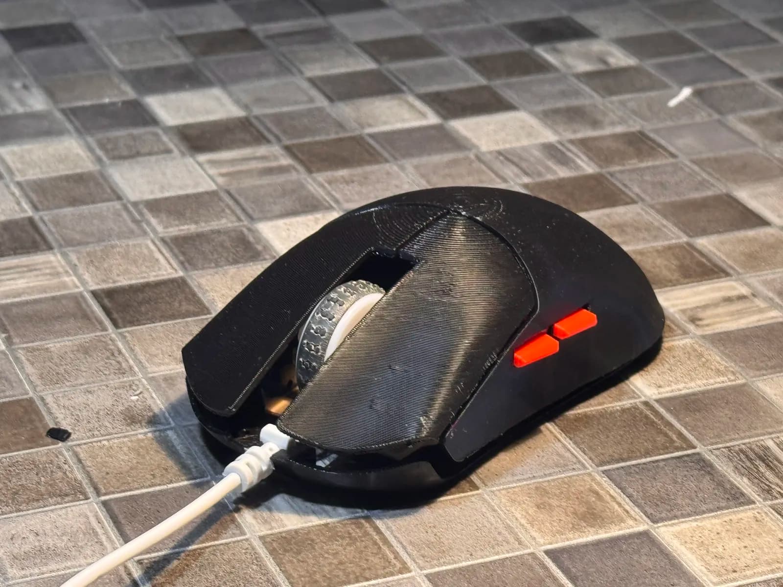
- The scroll wheel is not centred and sits at a slight angle. Off by just enough to notice for ever.
- The side buttons stick. They do not press cleanly and they jam. Step 9 of the assembly is optional for exactly this reason.
- The middle click does not exist. Not a geometry problem — the clone encoder I ended up with has no middle switch inside it at all. There is nothing to press.
- The main click is mushy and one press sometimes registers as several. My guess is the lever geometry. Either way it rules the mouse out for anything competitive.
- There is no cable grommet. I forgot to model the cover for the cable exit, so the cable is not locked down and can work its way out over time.
What I would change
Design for the bed, not only for the board
The single biggest mistake. Fit and printability are not competing goals if you think about both from the start — split the shell along a plane that leaves flat faces down, and most of the overhangs stop existing. I bolted printability on at the end, which is to say I did not.
NURBS was the wrong tool for an organic shell
A mouse shell is a hand-shaped blob with functional cut-outs in it. I built it entirely from trimmed NURBS surfaces, and closing that into a watertight solid is where most of the pain lived: surfaces that almost but not quite meet, tangency that goes wrong at the joins, naked edges small enough to miss and large enough to stop the thing joining into a closed polysurface. Then the mesh export inherits every one of those gaps.
SubD is built for exactly this shape. One closed cage, push it around until the form is right, and it stays watertight by construction — convert to NURBS at the end if you need the trimmed detail. Next organic body I model starts as SubD, and the surfaces come later.
Test the moving parts before printing the whole thing
A button lever is a hinge with a spring, and it needs a couple of iterations on its own. Printing a 40 g shell to find out that a 2 g lever feels wrong is the slowest possible feedback loop. Print the lever, the switch mount and nothing else, ten times, and only then the body.
Buy the encoder from someone who ships the switch
A scroll encoder with no middle-click switch is not a scroll encoder with a defect, it is a different part. Check the datasheet, not the listing photo.
Model the closure parts you cannot see
The missing cable grommet is a five-minute part that I did not think about because it is not visible in any render. Everything that touches the cable belongs in the model from day one.
Why publish it broken
The obvious move is to sit on a model until it is good. I think that is usually the wrong one for a project like this.
A polished model invites downloads. A broken one, documented honestly, invites a remix.
A shell that works but clicks badly is a specific, bounded problem that somebody with more CAD hours than me can fix in an evening — but only if the failures are written down. Hiding the mushy click behind a nice photograph wastes their time and mine. So the listing names every fault, and the source files are there in an editable format rather than as a mesh.
Consider it an open wound
Questions about the DeathAdder shell
Will this shell fit a DeathAdder Elite or a DeathAdder V2?
No. Every mounting hole, the sensor cut-out and the switch positions are built around the DeathAdder Essential board. A different DeathAdder generation has a different PCB outline, so the parts would have to be reshaped. The Elite is in fact what killed the original attempt this project inherited.
Which screws do I need for the build?
Three sizes: 3 x M3x5 hold the PCB to the base plate, 4 x M2x4 hold the button spring plastics, and 4 x M2x8 join the base plate to the top shell.
Does the model need supports?
Yes, a lot of them. The shell was shaped for fit and not for printability, so it has overhangs that no sane slicer setting will save. Splitting the parts and reorienting them for the bed is the single most useful remix anyone could make.
Does the middle click work?
No. The replacement scroll encoder I used is a cheap clone with no middle-click switch inside, so there is physically nothing to press. The wheel itself scrolls.
What files are included?
STL for printing, STEP for editing in any parametric CAD, and the native Rhino 3DM file if you want the NURBS surfaces rather than a mesh. Assembly photos are included too.
Can I remix the shell?
Please do. The shell is itself a remix of the EOS barebones mouse shell, so keep that credit chain intact and check the original model's license before you republish.
Get the files
- DeathAdder Essential — custom shell transplant on Printables: STL, STEP and the Rhino 3DM, plus the photo assembly guide.
- EOS, a barebones mouse shell — the original model this one remixes. Check its license before you republish anything derived from it.
Found another crime?